Case Study: Automated Shot Shell Loader
BACKGROUND
A small business ammunition manufacturer private labels the production of approximately 4 million 12 and 20 gauge shot shell rounds for a nationwide brand. The demand for this round is higher than the current production volume with top executives stating that 6-8 million rounds could be sold into the consumer market over the coming year if quantities were available. This demand taxes the current shotshell loading equipment – a dated assembly machine that is mechanically cam driven with little production feedback – beyond its capabilities.
Changing over from one SKU to another is costly. Typically requiring a full day of testing and setup to dial in the fully mechanical adjustments to make good rounds.
Many of the designed safety features had been bypassed or removed entirely while troubleshooting many issues over the years leaving the existing machine unsafe to operate. The machine no longer complied with current safety standards for equipment of this type.
Existing equipment limitations
- Unable to meet production demand.
- Requires costly changeovers.
- Unsafe.
| Current Metrics | |
|---|---|
| Equipment Uptime | 9 hours / Shift (10-hour shifts) |
| Actual average production | 18.5 PPM / ~10,000 per shift |
| Scrap per shift | 5% (500 rounds) |
| Cleanout Time | 30 mins |
| Changeover Time | 20 hours |
| Estimated Yearly Production | 4 million |
Simplified shotshell loading process:
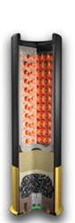
1. The Empty “primed” shell is loaded into the machine.
2. Powder charge is delivered to the shell.
3. Wadding is inserted.
4. Shot charge is delivered to shell.
5. A top card is placed.
6. Confirmation of components via length measurement.
7. Crimping.
GOAL and OBJECTIVES
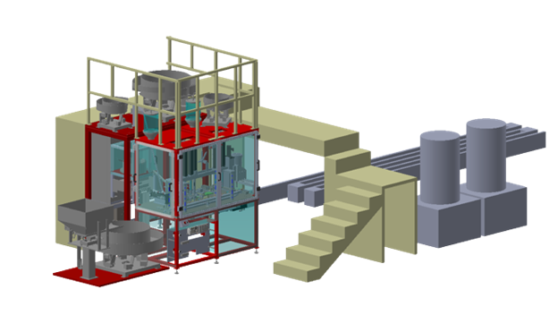
The goal of this project was to replace the existing automated loading equipment with an upgrade to a sophisticated servo driven assembly system.
Key objectives
- Increase assembly speed.
- Provide critical production information / improve quality to help prevent scrap.
- Implement an onscreen recipe management system to allow the operator to clean out the machine in minutes and changeover SKUs of different gauges in just hours instead of multiple shifts.
- Improve safety features.
Servo Machine Loading Process:
1. Primed Shell Infeed: Primed shells are bowl-fed to a vacuum feed. A cylinder drives them through an escapement and against a walking beam. The walking beam then indexes forward and moves the shells to the next position.
2. Belling Station: The walking beam indexes forward again, and the shells are captured by the inner rake. A servo expands the mouth of the shell to prepare for insertion operations and the walking beam indexes back to its starting position.
3. Powder Drop: A horizontal servo drops powder into the shell. An oscillating motion is used to ensure all powder is delivered from the chamber.
4. Gas Check (Over Powder Cup) Insertion: A cylinder drives a cup forward out of the nest, positioning it above the insertion bushing, and a servo drives the cup to depth above the powder charge.
5. Felt Wad Insertion: A cylinder drives a wad forward out of the nest, positioning it above the insertion bushing, and a servo drives the felt wad to depth above the gas check.
6. Shot Cup Insertion: A cylinder drives a cup forward out of the rear nest spring detents into a staging area. Simultaneously a slit cup is pushed forward above the shot cup insertion bushing. A servo drives the shot cup to depth above the felt wad. A slitting cylinder extends down to slit the cup.
7. Shot Charger: A servo extends forward to drop shot into the shell. An oscillating motion is used to ensure all shot is delivered from the chamber.
8. Overshot Card Insertion: A cylinder drives a card forward out of the nest, positioning it above the insertion bushing, and capturing it with spring pressure on the gripper fingers. A servo drives the card to depth above the shot.
9. Overall Length Inspection: A Keyence IX-150 non-contact laser height detection measures the length of the partially assembled shell. An incomplete shell is rejected if outside of the allowable standard length.
10. Crimp Station: Clamping cylinders to grip the shell at the base and prevent rotation. A servo equipped with a rotating motor and crimping tool extends down to apply pressure as the spin crimp motor rotates and creates the rolled crimp.
PROJECT SCOPE
Industry Tech Solutions was tasked with completing a partially developed project that had been stagnant for several years. When we received the project, the machine frame was only partially completed and lacked paint and safety guarding. Fixturing and tooling were only 50% complete, with only the walking beam, inner rake, servo mounting, and cylinder pushers present.
Our team was responsible for implementing the original concept into a fully functional machine. The project required significant engineering work, including the design of safety guarding, feeding systems, and insertion punches with tooling tips. We also completed the electrical design, which included panel layout, component specification, field I/O, and HMI panel.
Additionally, our team completed all wiring of components and programming for both the HMI and PLC Ladder.
Thanks to our team's expertise and hard work, we were able to take the project from a partial concept to a fully functioning machine.
RESULTS
The implementation of the new Shot Shell Loader has resulted in significant improvements in production efficiency and quality. The production rate has increased from 18.5 PPM (Parts per min) and approximately 10,000 rounds a shift to 24 PPM and approximately 13,000 per shift. This increase in production is attributed to the increase speed afforded to the system by having pre-operation conditions that prevent machine crashes.
In addition, the overall scrap rate has decreased from 5% to 2% of overall production. This improvement is due to the intelligent shell position tracking register and the IX-150 Laser sensor which measures the shell for proper length, ensuring all components are present before the crimping operation and before the shells are weighed for final packaging. This has resulted in better quality control and a reduction in wasted materials.
The changeover time has also significantly decreased from 2 - 10-hour shifts to 4 hours. Simple recipe changes now only require 5 minutes to perform. The recipe management system stores all setpoints and accurately reproduces the assembly without further mechanical adjustments. This has improved overall efficiency and reduced downtime.
Furthermore, all assembly processes are programmed with a set of pre-operation conditions that prevent assembly missteps and operator loading errors. The electric servo motors have torque fault settings to prevent damage during potential crash scenarios. The machine’s safety features non-contact door switches and remote E-stop locations on all sides. These safety features have increased the overall safety compared to the previous machine.
The usability of the machine has greatly improved as well. Being able to switch recipes and clean out the machine easily has increased the amount of time the machine generates good product. Operators have expressed that initial training on the machine was effective and the learning curve was very manageable. The new HMI display provides an increased amount of fault information and control.
Overall, the implementation of the new automated assembly line has resulted in a more efficient and higher quality production process. The improvements in production rate, reduction in scrap rate, decreased changeover time, and improved usability have all contributed to a better manufacturing process.
| Improved Metrics | |
|---|---|
| Equipment Uptime | 9 hours / Shift (10-hour shifts) |
| Actual average production | 24 PPM / ~13,000 per shift |
| Scrap per shift | 2% (260 rounds) |
| Cleanout Time | 5 mins |
| Changeover Time | 4 hours |
| Estimated Yearly Production | 5.4 million |
TECHNICAL INFORMATION
Feeding Systems
| 4 | Vibratory Feeders | Performance Feeders, Inc |
| 1 | Rotary Feeder | Custom |
| 2 | Gravity Funnels | Custom |
Part Presence / Part Confirmation
| 1 | OPT2031 | Automation Direct – Photoelectric Sensor – Shell Presence Confirmation |
| 1 | AHS-CP-1F | Automation Direct – Inductive Proximity Sensor – Primer Presence Confirmation |
| 4 | OPT2031 | Automation Direct – Laser Presence Sensor – Low Feeder |
| 2 | UK1A-GP-1E | Automation Direct – Tubular ultrasonic proximity sensor – Low Funnel |
| 1 | OPT2007 | Automation Direct – Discrete distance photoelectric sensor – Low Powder Delivery |
| 4 | OTP-2071, SSF-0P-0A | Automation Direct – Through Beam Fiber Optic, Amplifier |
| 1 | OPT2031 | Automation Direct – Laser Presence Sensor – Low Track OPC |
| 1 | CE1-CP-1F | Automation Direct – Capacitive proximity sensor – Low Track Felt Wad |
| 3 | AC1-CP-1A | Automation Direct – Inductive Proximity Sensor – Part Presence Escapement |
| 1 | OTP-2071, SSF-0P-0A | Automation Direct – Through Beam Fiber Optic, Amplifier – Part Presence Escapement |
Electrical Components – Assembly
| 11 | 2198-H008-ERS | Rockwell Automation – Kinetix 5500 Ethernet/IP Servo Drive |
| 8 | MPAI-B2300CV34A | Rockwell Automation – MP-Series Heavy Duty Electric Cylinder |
| 2 | MPAI-B2300CV34A | Rockwell Automation – MP-Series Heavy Duty Electric Cylinder (Spare) |
| 1 | MPAS-A60182-V20S4A | Rockwell Automation – MP-Series Integrated Linear Stage-Type Actuator |
Electrical Components – Control & Communication
| 1 | 1769-L36ERM | Rockwell Automation – CompactLogix 5370 Controller |
| 1 | 2715P-T15CD | Rockwell Automation – 15.0 in. Graphic terminal touch screen |
| 1 | EX600 | SMC – Ethernet I/P Serial Interface |
| 1 | DL-EP1 | Keyence – Ethernet I/P Communication Unit |
| 1 | IX-150 | Keyence – Image Based Laser Sensor – Overall length inspection |
Electrical Components – Safety
| 1 | XC26-2E | Banner - Expandable Programmable Safety Controller |
| 4 | 440N-G02099 | Rockwell Automation - Guardmaster 440N Non Contact Switch |